Conductivity Measurement: Critical for Clean-In-Place Systems
Clean-in-place (CIP) technology, the automatic, reproducible and reliable delivery of cleaning solutions and rinse water through process equipment and piping, offers significant advantages to pharmaceutical and life sciences manufacturing facilities. The ability to clean a processing system — incorporating tanks, pumps, valves, filters, heat exchange units and process piping — without having to disassemble all or part of the system is a lowercost, regulatory-compliant solution. Cleaning-in-place also increases efficiency, improves safety, avoids crosscontamination, and ultimately, provides higher assurance of product quality.
However, achieving these benefits requires tight measurement and control of the CIP process. A plant manager must use the appropriate amounts of cleaning solutions and be able to determine reliably that those solutions have been removed completely before the next processing run or campaign. Conductivity analysis can help confirm those processes. Since the various cleaning solutions are more conductive than the water used for flushing, conductivity measurement is a logical way to monitor the cleaning steps and the final rinse. This article will review the proper use of conductivity measurement in CIP systems, and discuss advances in conductivity analysis.
How CIP Works
The key objectives of an efficient CIP system are:
- Maximize safety — to avoid cross-contamination.
- Minimize CIP time — to help speed time-to-market and reduce impact on plant production.
- Optimize thermal efficiency — to avoid unnecessary heat loss and reduce energy requirements.
There are multiple configurations of CIP systems available, the two most common being single-use and multi-tank. In other industries, multi-tank systems are typically used to provide for the recycling of water and possible regeneration of cleaning chemicals. There is, however, a greater risk of cross-contamination with this configuration. Pharmaceutical and life sciences manufacturers typically employ multi-tank systems, but use them as single-use systems, with the tanks being drained between programs to minimize the potential for cross-contamination. Each of the multiple stainless steel tanks holds a different quality grade of water, such as deionized water (DI), hot or cold water for injection (WFI), and water for reverse osmosis units (RO).
The CIP process involves multiple cycles including an initial and final drain step, a pre-rinse, a sodium hydroxide wash and a post-rinse. Rinse and wash cycles vary from five minutes to one hour. The process may include a “sanitize” cycle to reduce the levels of bacterial contamination using strong oxidants such as hydrogen peroxide, ozone, chlorine dioxide or other chlorine-containing compounds. Thorough removal of these chemicals is required to prevent cross-contamination and to avoid corrosion of the stainless steel apparatus.
When the CIP process is initiated, pre-rinse water is sent through the circuit and “chases” the product. A timing sequence based on distances and flow rates will switch the valves at the proper time to minimize the interface between product and rinse water. Over 90% of the product residue is removed during pre-rinse in order to minimize the use of washing chemicals. Proper cleaning (as determined by FDA) is a function of detergent strength, cleaning time and temperature.
Figure 1: CIP equipment/process configuration.
Where Conductivity Works
Conductivity measurement plays a key role in the following CIP stages and functions:
-
CIP acid and caustic detergent concentration
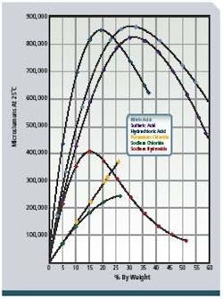
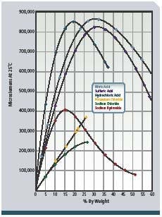
To provide detergent of the proper concentration for each CIP circuit and to validate that cleaning was done at the proper detergent strength, conductivity measurement is applied to the returning acid and caustic. These conductivity measurements are proportional to the concentration or solution strength (see Figure 2, below) and are recorded by control systems for validation. The fluids are often partially neutralized during the CIP process, and additional concentrate dosing is required. Conductivity indicates when sufficient concentrate has been added to the appropriate tanks. Figure 1 shows a typical configuration. -
CIP/process interface and CIP completion
Because the various cleaning solutions are more conductive than the water used for flushing and final rinsing, conductivity measurement is a cost-effective way to monitor the CIP steps. It is highly effective at detecting the interface between cleaning solutions and the product so that the valves can be switched at the appropriate time to minimize the interface between the two and any resulting product loss. Conductivity measurement can also determine the interface between cleaning fluids and rinse water to minimize CIP time while meeting compliance requirements. When the conductivity drops to the value of rinse water, it indicates that the water is running clear, prompting the next step or the end of the cycle.
Selecting the Right Conductivity Sensor
Conductivity sensors used in CIP applications must be of sanitary design. This means the sensor surface should not have contours or crevices that could trap residue from the product and cause decay or harbor microorganisms that would result in cross-contamination. They also must be made of FDA-approved materials.
There are two main types of sanitary conductivity sensors — contacting and inductive. Contacting sensors bring the measurement electrodes into contact with the solution to be measured. This can be a problem if the solution can foul or corrode the electrodes. Inductive sensors are non-contacting and are often called toroidal because they use toroidal transformers isolated from the process. One toroid acts as a transmitter and the other as a receiver. The transmitter toroid produces an electric current in the process solution that induces a voltage in the receiver toroid. The strength of that induced voltage is directly proportional to the conductivity of the solution.
Inductive sensors (traditionally used to measure the caustics and acids in the CIP process) also come in two types. Standard inductive sensors have a donut shape and are inserted into the pipe where the measured solution flows around and through them. This type of sensor is frequently used in applications with line sizes greater than two inches, as the sensor does not impede flow. For applications with line sizes of two inches or less, an inductive flow-through sensor may be ideal. In this configuration, the sensor is not inserted in the pipe, but is clamped into the process piping between flanges. Because the sensor is virtually a part of the pipe, it does not impede flow.
Figure 2: Concentration vs. conductance of NAOH (sodium hydroxide)
and other chemicals.
However, these traditional rules regarding sensor selection are changing, due to one of the most important issues in CIP conductivity measurement — dynamic range.
Expanding Dynamic Range and Noise Performance
A significant challenge in CIP conductivity analysis is that the process involves two distinctly different conductivity measurement ranges — one for moderate-to-high concentrations of acid and caustic, and the other for the purified rinse water. Therefore, the process has tradition-ally required two conductivity sensors — one with a high cell constant required to measure >100mS/cm, and one with a low cell constant equipped to measure the <10μS/cm of ultrapure water.
Typically, the caustic is measured with an inductive conductivity sensor or four-electrode contacting conductivity sensor, while the purified rinse water is measured with a two-electrode contacting conductivity sensor. Since two-electrode contacting conductivity sensors become non-linear on the high end of the conductivity range, and inductive or four-electrode conductivity sensors do not measure accurately at the low end of the conductivity range, traditionally, two sensors have been required for the application. In fact, some applications have simply measured the cleaning solutions and ignored the rinse water due to the added cost and complexity of using a totally different type of sensor and an additional analyzer.
However, new technology has made it easier for the plant manager wanting to implement a CIP system without excessive cost and complexity. First, dual sensors — with a single, multi-channel analyzer having multi-ranging measurement capabilities — are available. This reduces cost and simplifies data collection, operator training and control.
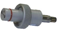
Another recent development is a single sensor that is capable of measuring the full dynamic range, from <2μS/cm to 600mS/cm. Using four-electrode contacting conductivity technology and made of virgin PEEK (polyetheretherketones), this sensor is highly resistant to damage from cleaning solutions. Improvements to the analyzer’s signal conditioning allow excellent resolution on both the low end and high end of the conductivity scale while maintaining linearity.
Figure 3: Rosemount Analytical PUR-Sense conductivity sensor.
Key to the advances in dynamic range of the new sensors is better noise-suppression technology. Since conductivity is sensitive to noise produced by CIP components such as the pump, the result has often been greater variance in conductivity readings. Now, manufacturers are using a combination of software, improved isolation techniques and enhanced microchips to render noise a non-issue.
Selecting Automation Technologies
Due to stringent FDA reporting requirements, plant man-agers must address automation technologies with a broad view. Historically, CIP systems have been controlled by PLC (programmable logic controller)-based systems with 4-20 mA inputs from the measurement devices. This has resulted in what are often called “islands of automation,” wherein separate records are kept between the operations part of the plant and the individual utilities, including CIP.
The current trend is to integrate critical utilities such as CIP and WFI with the operational units. Distributed control systems (DCS) using intelligent measurement devices with Foundation fieldbus, Profibus or HART communications protocols allow for a better designed operation. CIP demand can be rolled into the plant’s control system strategy.
Digital communications from the measurement devices allow electronic records such as configuration methods, calibration events, and alarm conditions to be stored in a single database. Digital communications also provide for the increasingly sophisticated diagnostics available in today’s liquid analysis systems. Measurement devices with diagnostics can help troubleshoot start-up (where problems may include a miswired sensor transmitter) and oversee ongoing operations. Selecting devices with embedded “Help” files can facilitate troubleshooting. Users can determine the root cause of a measurement fault along with recommended actions to get the measurement back to an operational condition. While digital communications may add to upfront costs, the benefits in enhanced productivity, timely and accurate reporting, and automated control cannot be overstated.
So, while conductivity measurements may seem like a small cog in a very large pharmaceutical and life sciences manufacturing wheel, they are critical to the success of a CIP program. Fortunately, technological advancements in conductivity analysis are making the application of this measurement simpler and more cost-effective. With just a little attention to detail, conductivity analysis can provide a wealth of vital information.
About the Author
Dave Anderson is Life Sciences Industry Manager at Emerson Process Management, Rosemount Analytical, Liquid Division (www.raihome.com). He has more than 17 years of industry experience and can be reached at 949-757-8500.


