Product security concerns and regulatory pressure have led to the gradual adoption of electronic pedigree solutions throughout the industry. Secure e-pedigree files store data about each move products make through the supply chain and are intended to allow for the tracking and verification of pharmaceutical products from the time of manufacture to end use. As with many new technologies, however, e-pedigrees have a variety of issues to overcome. One if them is the creation of machine vision inspection systems that can reliably identify and decode the complex markings on bottles and caps that carry e-pedigree information without impeding the flow of manufacturing.
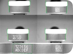
A 2D data matrix, widely used in the automotive and food and beverage industries, has emerged as the primary method for encoding the required information (see Figure 1). This matrix holds large amounts of data, but incorporating it into existing pharmaceutical manufacturing flows involves placement of data on a package not originally designed to accept this information. This must be done in a permanent, legible fashion while accounting for the need to use this information at various user and distribution points. Additionally, the restrictive nature of pharmaceutical packaging does not allow for much in the way of material changes to easily accommodate new markings that must have high contrast so that scanners and imaging systems can read them.
(Click to enlarge image) Figure 1. The 2D code (upper left of label) can contain significant amounts of information regarding content, dosage and production history.
Another challenge is that markings may be located anywhere on the bottle and cap, and in many different forms, ranging from black-on-white inkjet markings on paper to silver-on-black markings on a metallic cap. Add to this the fact that a given manufacturing line (thus the inspection system) must accommodate a variety of different bottle sizes, label placements, materials and even color schemes to handle different production runs. These many constraints create significant challenges in the design of a machine vision system that can automatically detect and read the 2D matrix.
Looking for a Solution
Packaging equipment designer and manufacturer FP Developments (Williamstown, N.J.), working with the support of Edmund Optics (Barrington, N.J.) and Cognex Corp. (Natick, Mass.) confronted these challenges to develop a machine vision system that could thoroughly and accurately inspect e-pedigree data. The system had a requirement to efficiently move hundreds of bottles a minute from a filling and labeling area to a gross packing area while ensuring that each bottle was labeled and marked correctly. The labeling on the caps, and in some instances on the bottles, needed to be read with a high degree of accuracy at all times. Further, the material handling portion of the system had to target what is called toolless changeover — that is, be able to handle a variety of different containers quickly and easily without the need to install new fixturing or make complex changes to the line.
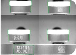
A key consideration for manufacturing engineers that can impact the machine vision system is the placement of the 2D barcode and how it is laid down. Placement must reflect the fact that everyone from distribution companies to doctors and hospitals will need to read the barcodes. One common choice is to mark the cap skirt (Figure 2) so that labels do not need to be re-designed.
(Click to enlarge image) Figure 2. The cap skirt provides a convenient location for adding a 2D code without requiring label redesign but presents machine vision systems with challenges for automatic reading, including variations in orientation, bottle height, material reflectivity and marking method.
The marking technique can range from imprinting a code with a printer, to burning in the code with a CO2 or YAG laser, to use of markings that can only be seen under UV. Each method has pluses and minuses that must be considered in light of factors such as the type of cap used on bottles and the speed at which they pass through the system, as well as cost, intended product use and bottle materials. A critical issue is producing enough contrast in the printing for it to be viewed from almost any angle. The higher the contrast, the more accurately the vision system can read the data.
Another issue is that the system does not know in advance exactly where in its field of view the marking will be located. Not only will label placement and bottle size vary from one product line to another, the orientation of the bottle when it reaches the inspection stage will vary. Manufacturing systems that move bottles typically have at least one stage where the bottle will roll or spin an indeterminate amount. Creating a means of ensuring that the bottles all have a consistent orientation would be too costly, so the vision system must be able to accommodate this uncertainty.
FP Developments addressed this problem by designing its system to use multiple cameras that look at all sides of the bottle simultaneously. While it can seem fairly simple to set up three or four cameras to inspect an object, it can be difficult to extract the resulting information. The marking may wrap around the edges of the object and thus have sections appear spread across two different images, each distorted by the curvature of the surface. Cognex has addressed this problem in its Omni View platform, which uses four high-resolution cameras and proprietary software algorithms to take multiple images and create a 3D surface model image of an object, then flatten it. From this flattened or unwrapped image the machine vision system can extract a host of information by using standard image analysis algorithms.
Camera and lens selection and lighting were the next issues to resolve. Cameras must be fast enough to capture images as bottles move past at production speeds, have a wide enough field of view (FOV) to encompass the marking, and have enough resolution to enable reading of the 2D code. Lens selection is critical because distortions or blurring across the camera’s FOV, including insufficient depth of field to accommodate the bottle curvature, can affect the image analysis algorithm’s accuracy. Similarly, variations in lighting intensity across the FOV, and the presence of shadows, highlights and reflections, can compromise the algorithm’s ability to reliably extract information.
There are system factors to consider in the selection of camera, lens and lighting for a specific manufacturing line as well. These include:
- Bottle size
- Bottle position relative to camera position
- Depth of field relative to the curvature of the cap
- Object area to be imaged (in some instances, only the cap or both the cap and label on the bottle needed to be imaged)
- Potential for the cap, cap skirt and label to be made in different colors, textures and materials.
- Striking a balance between single large field of view that can image any size bottle vs. obtaining enough detail from the relatively small, potentially low contrast 2D bar code
- Speed of the production line
- Amount of room available to fit four cameras and lenses into the production line
- Ability to insert the inspection station into the flow without significantly altering the remaining equipment
Selecting the Components
Based on the dimensions of the installation, the camera selected had a 2-megapixel resolution with pixel size of 4.4 µm. But the number of lens options very quickly reduced to a few choices. The lenses needed to provide sharp images with an adequate depth of field, a two-inch FOV, and wide enough aperture to obtain high levels of contrast at short distances in order to take full advantage of the software algorithms.
Many lenses used in machine vision today were designed for either multipurpose use or for industries that do not necessarily address high-resolution imaging at short distances. The demands of this application required lenses specifically dedicated for high-resolution machine vision at short conjugates. The resolution of the lens, which affects the sharpness of fine details, should both match the camera pixel size and be uniform across the FOV (yet it is typically only specified for the center of the FOV). Further, small changes such as dilating the iris within the lens can affect resolution.
FP worked with its own engineers and those from Edmund Optics to match lenses and cameras. The team was able to select a stock EO product that had the right combination of FOV and working distance for use in the space available with lens resolution to match the camera and imaging detail requirements.
One of the trickiest parts of the application was lighting. Objects that seem simple, like a small clear bottle with an aluminum lid, are some of the hardest to illuminate evenly without hot spots or glare. This is especially true when considering that the bottle must be viewed from all sides. Bottles can be both clear and highly reflective at the same time and, if filled with liquid (having different indices depending on what is being run), can act as a lens for the lighting. Thus, a light illuminating one side of a bottle may reflect or be lensed to form a hot spot in the image on another side. Moreover, the reflectivity of the surface with the marking can vary from part to part and run to run.
Because any sort of directional illumination would create hotspots, diffuse illumination needed to be employed. Diffuse illumination that is large relative to the object creates a “cloudy day” effect that will not produce any hot spots or lensing. Glare, however, remains a problem with curved surfaces even with diffuse illumination. Thus, the diffuse lighting needed to have a curved geometry similar to that of the bottles and caps in order to flatten glare off the surfaces. To provide this curved geometry, the design uses a large diffuse dome light positioned directly above the bottles to create the desired effect. The dome bathes each bottle with diffuse illumination from a large curved light source, creating very even illumination from all directions.
Unfortunately, the intensity of diffused light sources can drop off very quickly as their distance from the object increases. Increasing the dimensions of the light source can compensate somewhat, but the space constraints of the installation limited what could be implemented. As a result, with lighting from the dome alone the bottom of the bottle was far darker than the top — not compatible with the image analysis algorithms.
Solving Illumination Challenges
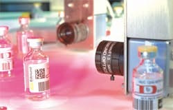
The engineers looked to a non-conventional lighting method that took advantage of the bottle carrier mechanism. In this installation, the bottles move on a flat carrier (Figure 3) while a vacuum system holds them from below so that they do fall over or fly off as they move through the viewing area. The vacuum connection made placing a lighting system directly below the bottles impossible. This allowed conversion of carrier to a secondary light source to illuminate the bottle from the bottom. Fiber optics direct light to the edges of the carrier as it moves in front of the cameras and the translucent material scatters that light in all directions, thus serving as a diffuse light source from beneath the bottle. By balancing the intensity of the dome light with the light piped into the carrier, the system can achieve highly uniform illumination across a variety of bottle sizes.
(Click to enlarge image) Figure 3. The final design utilizes machine-vision specific lenses on four cameras with software that merges and flattens the four images for processing, and employs the bottle carrier as a secondary lighting source.
The resulting vision system was thus flexible enough to accommodate bottles of varying sizes holding 2D codes set in various places using different marking techniques. Such flexibility was essential to meeting the need for toolless changeover while maintaining the accuracy needed in imaging and extracting the data codes off pharmaceuticals.
About the Authors
Gregory Hollows is director of machine vision solutions for Edmund Optics. David Pfleger is vision project coordinator for FP Developments.


