In June of 2002, ground was broken for a new Bioprocess Development Facility at the Wyeth site in Pearl River, N.Y. Primary applications for the new building included process development and manufacturing of highvalue products from microbial fermentation.
Installing new equipment — 14 skid-mounted fermenters with working volumes ranging from 75 to 1000 liters — represented a key element of the facility’s design. The design required that each of the process skids be fully automated through the use of a modern, integrated process control system that would permit full batch automation in accordance with ISA’s S88 standard.
It was also essential for the fermenters to be equipped with instrumentation and controls that connected to the process control system through the use of fieldbus technologies.
A fieldbus is an industrial process control network at the lowest level of the process control hierarchy; it is used to connect measurement and control equipment to the process controller.
Conventional instrumentation and controls use a pair of wires for each device to carry analog signals for communication. In contrast, fieldbus instrumentation and controls use a digital network that permits the instrumentation to communicate with the other instruments and the process controller. With a fieldbus, a network of field devices is connected to the process controller via a pair of wires.
These wires provide bidirectional communications from multiple transmitters and control devices to the process controller. Fieldbus instrumentation for process applications comes in a variety of forms, including AS-i bus, DeviceNet, Ethernet/IP, Foundation fieldbus and Profibus. Open system standards and vendor product certification are available from independent foundations and associations of vendors for each fieldbus type.
Taking the Bus to Pearl River
Following the completion of a bid evaluation process for fermentation equipment, Sartorius BBI of Allentown, Pa., was selected to provide the fermentation skids. Emerson Process Management was chosen as the automation supplier for different reasons.
he group responsible for bioprocess development at the Wyeth Pearl River facility had been using an Emerson DeltaV process control system for fermentation process control since 1997. This system was installed in a building scheduled for demolition when the new Bioprocess Development Facility had been completed and occupied. Therefore, Wyeth elected to move the license for the existing system and some of the process control system elements to the new building.
Computer hardware, control cabinets and software versions would be upgraded with the move. Although the DeltaV process control system was originally installed in 1997, it had been upgraded in 2000 to include fieldbus instrumentation and controls. Foundation fieldbus temperature transmitters from Rosemount and pH transmitters from Rosemount Analytical were installed using a DeltaV Foundation fieldbus H1 communications module, and AS-i bus relay controls were installed using DeltaV AS-i bus communications.
Since the upgrade, Wyeth operating personnel had been impressed with the stability and reliability of the Foundation fieldbus devices and with the extensive diagnostic and calibration features available when used with the DeltaV process control system. The simplicity and compact design of the AS-i bus relays compared favorably with the hard-wired relays that they replaced. Wyeth’s experiences with these two fieldbus systems — Foundation fieldbus and AS-i bus — led to the decision to specify fieldbus designs for the new plant.
The new facility was intended not only to replace existing facilities, but also to add new functionality. For example, the DeltaV process control system in the new plant was configured to support the manufacture of both clinical and commercial products from microbial fermentation.
Good Manufacturing Practices dictated that the computer process control system be qualified along with all of its field instrumentation and controls. At Wyeth, the standard for computer control system qualification is based upon the GAMP 4 Guide for the Validation of Automated Systems1 published by ISPE in December, 2001.
Automation System Design
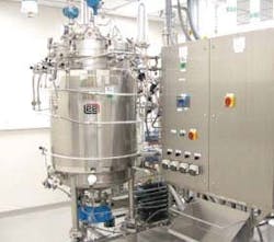
One of the fermenter skids provided by Sartorius BBI is shown in Figure 1 (below). The skid vendor specified the instrumentation and controls in accordance with guidelines provided by Wyeth. Because of Wyeth’s previous experience with Foundation fieldbus and the DeltaV process control system, Foundation fieldbus transmitters and control elements were preferred. However, many of the instruments and controls needed to automate fermentation processes were not available as Foundation fieldbus devices.
Figure 1. A 400-liter working volume fermenter supplied by Sartorius BBI.
In those instances, Sartorius BBI chose to use instrumentation and controls based on Profibus DP. In general, two-wire devices powered by the fieldbus were available as Foundation fieldbus devices, and fourwire devices powered from the field required a Profibus DP interface.
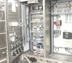
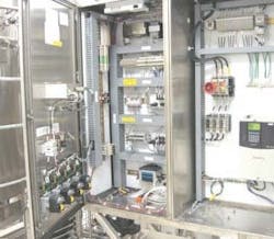
With the choice of these two fieldbusses, the fermenter skids could be controlled by two wired connections to the DeltaV process control system — one wire for Foundation fieldbus and one wire for Profibus DP. Instrumentation selected by Sartorius BBI for the fermenter skids included sensors for pressure and batch and jacket temperature from Rosemount, a Fisher pressure control device, and sensors to monitor pH and dissolved oxygen from Rosemount Analytical. Figure 2 (left, bottom) shows the fermenter control cabinet.
For the Foundation fieldbus devices, a single wire entered the cabinet for connection to a Relcom fieldbus connector block. Each of the Foundation fieldbus devices was then wired to the central block.
Figure 2. Fermenter control cabinet with fieldbus connectors.
In contrast, Profibus DP requires that each device be wired in sequence with either a Profibus DP sub-D connector or a Euro type 5-pin connector. The installation of busbased instrumentation and controls resulted in a clean, uncluttered design because fewer wires, interface devices and controls were installed on the process skid than would be needed for a conventional design.
Monitoring and control functions accessed through the fermenter display faceplate are based on field devices that communicate through a Foundation fieldbus network or through a Profibus DP network. The “mass spec” exhaust gas monitoring readings present an exception. The exhaust gas monitoring system is one of several secondary applications installed in the facility to support microbial fermentation.
These secondary applications also include the monitoring and control of a biowaste system, the control of portable clean-in-place systems, the monitoring of ultra-lowtemperature freezers, the monitoring and control of product recovery equipment and the monitoring of an environmental control system.
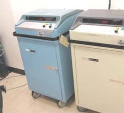
For each of these secondary applications, fieldbus-based instrumentation and controls were specified, whenever possible, but in specific instances, conventional instrumentation was required. Fermentation exhaust gas monitoring is performed using PerkinElmer Model 1100 medical gas analyzers (Figure 3, right).
Figure 3. PerkinElmer Model 1100 medical gas analyzers.
These analyzers measure carbon dioxide, oxygen, and nitrogen in the fermentation exhaust gases and provide the three measurements as 0-10 volts outputs. The three voltages are converted to 4-20 milliamp readings and read by a conventional DeltaV analog input module. Exhaust gases are directed to the mass spectrophotometers by a 32-channel exhaust gas manifold (Figure 4).
AS-i bus signals are used to control the 20 Stonel dual relay devices. A complex 32-channel sequential function chart (SFC) program is used to control the exhaust gas manifold, read the data, and perform calculations during a fermentation batch. Located in the basement of the new facility are two biowaste vessels that sequentially collect and process contaminated condensate waste from each of the fermenter skids. One of these vessels fills to a specified level before it is heated to sterilizing temperatures for a period of time, cooled, and then drained.
The temperature and pressure transmitters are Foundation fieldbus devices. The digital I/O is based on a Festo Profibus DP solution. However, liquid level is measured by a conventional 4-20 milliamp Hart device that was not available in a fieldbus implementation. Two portable clean-in-place systems are used for cleaning the fermenter skids.
Figure 4. The 32-channel fermentation exhaust gas manifold.
Connection to the DeltaV system is via a single Profibus DP wire. Although two conventional 4-20 milliamp transmitters are mounted on the skids for conductivity and level, Festo CPX analog modules are used to communicate the analog signal readings to digital readings for transfer to the DeltaV system via Profibus DP.
A Yokogawa Daqstation paperless chart recorder for freezer monitoring includes a Foundation fieldbus interface. Although the recorder can store data, the Foundation fieldbus interface to the DeltaV control system permits the use of the DeltaV continuous historian for data archiving.
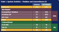
The paperless chart recorder provides a local display of 72 hours worth of trending in the freezer rooms, while the permanent record resides on the DeltaV system. DeltaV Process Control System I/O statistics are shown in Table 1 (below).
The DeltaV system includes 572 input/output points, of which 96% are networked, bus-based I/O. Only 4% of the I/O on the system is based upon analog instrumentation. The DeltaV system control cabinet has three DeltaV M5 controllers mounted on carriers with space for 16 I/O modules.
The second controller mounted on the middle carrier uses only three modules to monitor and control six fermentation skids. The modules include one Foundation fieldbus H1 module, which provides two independent field network segments, and two Profibus DP modules, which provide a single field network segment.
The monitoring and control of six fermenter skids represents a loading of 15 devices on each Foundation fieldbus H1 segment and 12 devices on each Profibus DP segment. The third controller on the bottom carrier includes an AS-i bus module and a single conventional analog input module for exhaust gas monitoring and manifold control. Controller 1 on the top carrier includes two Foundation fieldbus H1 modules, three Profibus DP modules, a digital input module, and two analog input modules.
The additional modules on this carrier were required for many of the secondary applications that have been described.
Editor’s Note: Look for Part 2 of this article in our January issue.
References:
1. GAMP Guide for Validation of Automated Systems (GAMP4) published by ISPE, December, 2001.
About the Author
Gary Forrest, Ph.D., is Associate Director– Bioprocess Development, Wyeth Research, Pearl River, N.Y.
