As the philosophy and techniques enshrined in Quality by Design (QbD) become second nature to the pharmaceutical industry, their application is spreading. Analytical method development is a current area of focus. The process of developing, validating and deploying analytical methods closely parallels product development and can similarly benefit from the systematic and scientific approach that QbD promotes. The dependence of pharmaceutical development and manufacture on robust analytical data intensifies the need for rigor in analytical method development and increasingly a QbD approach — Analytical QbD (AQbD) — is seen as the way forward.
THE GOAL IS TO DEVELOP
In analytical method development the goal is to develop, validate and deploy a method for making an analysis that will deliver the information required, in all the instances that it is required to do so. The starting point is to identify exactly why the measurement is being made; in the same way that the starting point for conventional QbD is to identify clinical performance targets for the product. Once this is established, the process is one of understanding and learning to control those aspects of the measurement method that define critical elements of analytical performance. This closely mirrors the QbD model of working toward a fully scoped design space.
INTRODUCING THE PRINCIPLES OF QBD
A useful starting point for examining AQbD is to return to the generally accepted definition of QbD, which was originally presented in International Conference on Harmonization document Q8(R2). This states that QbD is:
“A systematic approach to development that begins with predefined objectives and emphasizes product and process understanding and process control, based on sound science and quality risk management …”
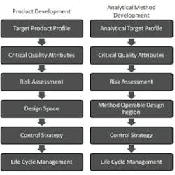
Figure 1 shows the QbD workflow that represents this systematic approach. The first step is to identify the Quality Target Product Profile (QTPP), the definition of what the product must deliver. The subsequent steps of QbD involve identification of the variables that must be controlled to deliver the defined product performance, and the best way of implementing that control.
QbD workflows for product devvelopment and the analogous workflow for analytical method development
CONTINUOUS IMPROVEMENT WRAPPER
Determination of performance-defining Critical Quality Attributes (CQAs), and the Critical Process Parameters (CPPs) and Critical Material Properties (CMAs) that control them, comes first. Definition of the design space follows. The design space is the operating envelope for the process. It encompasses the defined ranges for the CPPs and CMAs that ensure the CQAs will be achieved consistently. Defining the control strategies needed to maintain operation within the design space is the final step, but the entire workflow is wrapped within a process of continuous improvement across the lifecycle of the drug. Indeed, a major attraction of QbD is that its application permits ongoing optimization within the design space without requiring further regulatory approval.
ICHQ8 (R2) does not specifically mention analytical method development. However, the underlined phrases in the original QbD definition (above) have direct resonance when looking to apply a structured, rigorous approach to developing analytical methods. This resonance has prompted the evolution of Analytical Quality by Design (AQbD).
TRANSFERRING QBD TO ANALYTICAL METHOD DEVELOPMENT
FDA guidance on the application of AQbD [1] highlights the potential benefits of transferring QbD to analytical method development. The proposal is that AQbD will lead to the development of a robust method that will be applicable throughout the lifecycle of the product. Just as with QbD, being able to demonstrate adherence to AQbD will be associated with a certain degree of regulatory flexibility, providing the freedom to change method parameters within a method’s design space, referred to as the Method Operable Design Region (MODR).
The starting point for AQbD is an Analytical Target Profile, or ATP, which is directly analogous to a QTPP (Figure 1). The ATP defines the goal of the analytical method development process, linking the output of the method to the overall QTPP. Identifying why the analytical information is required, what it will be used for and when, helps to formulate the ATP. Supplementary targets for performance characteristics, such as precision and reproducibility, stem from a more detailed analysis of these needs.
The next step is to identify a suitable analytical technique. This must be done with reference to the needs defined in the ATP. Once the technique is identified, AQbD focuses on method development and includes detailed assessment of the risks associated with variability associated with:
• Analyst methods
• Instrument configuration and maintenance
• Measurement and method parameters
• Material characteristics
• Environmental conditions
This assessment identifies the CQAs, the parameters that impact the ATP. A Design of Experiments (DOE) approach is then adopted to define the MODR. This is the operating range for the CQAs that produces results that consistently meet the goals set out in the ATP. Once this is defined, appropriate method controls can be put in place and method validation carried out following the guidance in ICH Q2.
Like QbD, AQbD works on the principle of recognizing and handling variability by understanding its potential impact. By identifying an analytical design space, rather than applying a fixed set of measurement conditions, it enables a responsive approach to the inherent variability encountered in day-to-day analysis throughout the lifecycle of a pharmaceutical product. This delivers an analytical method that is robust in daily use and which also substantially reduces the potential for failure when the method is transferred from, for example, a research laboratory through to QC. The root causes of method transfer failure can usually be traced back to insufficient consideration having been given to the nature of the routine operating environment and a failure to capture and transfer the information needed to ensure robust measurement. Applying AQbD overcomes these issues and has the potential to eliminate costly mistakes.
DEVELOPING A PARTICLE SIZING METHOD
Addressing a specific analytical challenge helps to clarify what the application of AQbD looks like in practice. Consider the scenario of measuring the particle size distribution of a micronized active pharmaceutical ingredient with the goal of assessing its suitability for downstream processing and bioavailability for a solid oral dose product.
In this situation the ATP is the measurement of particle size distribution at a defined point in the process, in a way that is precise enough to ensure the material will perform to expectations. In practice, the required level of precision may exceed that which is laid down in the US and European Pharmacopoeias [2, 3], but for simplicity we will assume that the USP and Ph. Eur. acceptance criteria are adequate. Many techniques are available for particle size distribution measurement, but laser diffraction is the method of choice for most pharmaceutical applications. So we will base this AQbD example on laser diffraction particle size measurement.
Laser diffraction analyzers determine particle size from the pattern of scattered light produced as a collimated laser beam interacts with particles in the sample.
INTRODUCING LASER DIFFRACTION
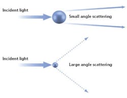
Fast, non-destructive and amenable to automation, particle sizing by laser diffraction is a technique that has been tailored in modern instrumentation for high productivity, routine use. In a laser diffraction particle size analyzer, the particles in a sample are illuminated by a collimated laser beam. The light is scattered by the particles present over a range of angles, with large particles predominantly scattering light with high intensity at narrow angles, and smaller particles producing lower intensity signals over a much wider range of angles. Laser diffraction systems measure the intensity of light scattered by the particles as a function of angle and wavelength. Application of an appropriate light scattering model, such as Mie theory, enables particle size distribution to be calculated directly from the measured scattered light pattern.
Laser diffraction involves relatively little sample preparation, but it is essential to present the sample in a suitably dispersed state to generate data that are relevant. In our example, the need is to measure the primary particle size distribution of the active pharmaceutical ingredient. This means that any agglomerated material present must be dispersed, prior to measurement, to ensure consistent and relevant results. Here then the parameters applied to ensure complete dispersion are CQAs, variables that have a direct impact on the quality of the results. Investigating dispersion in a systematic way is therefore a primary objective when it comes to defining the MODR for a laser diffraction method.
SCOPING THE MODR
When it comes to dispersing a sample for laser diffraction particle size measurement, there is a choice to be made between dry powder or liquid dispersion. Dry dispersion is the preferred option because it:
• Enables rapid measurement to be made,
• Is well-suited to moisture-sensitive materials,
• Accommodates relatively large sample volumes, enabling reproducible measurement of poly disperse materials, and
• Is environmentally benign, as the use of organic liquid dispersants is avoided.
Although dry dispersion offers these advantages, it is not suitable for all sample types. Dry dispersion involves entraining the sample within a high-velocity air stream. The process of entrainment subjects the particles to substantial shear energy and promotes particle-particle/particle-wall collisions, dispersing any agglomerates.
Friable materials may be damaged by this process. It may also be hazardous to handle highly active ingredients in this way because of the risks associated with aerosolization. Some samples are therefore better suited to liquid-based measurement.
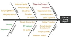
Output of an assessment of the key parameters for a dry dispersion method. Items shown in green are noise factors with the method; those in orange are control factors; whereas those in red must be investigated experimentally to determine the MODR.
Figure 3 shows some of the CQAs associated with a dry method for a micronized API powder. In dry dispersion, the air pressure applied during entrainment of the sample is the lever that is used to control the input of energy into the dispersion process. This identifies it as a CQA. Another consideration is the sample feed rate, as this determines the amount of material which passes through the venturi during the dispersion process and therefore the efficiency of dispersion. It also defines the concentration of a sample, which in turn can have an impact on the measurement process itself. If particle number/density is too low, then the signal to noise ratio during measurement may be unreliable. Conversely, a high particle density increases the risk of multiple scattering, where the light interacts with more than one particle prior to detection, a phenomenon that complicates the calculation of particle size. Feed rate, therefore, tends to be the other CQA when using dry dispersion for laser diffraction particle size measurements.
So, working on the basis that dry dispersion is suitable for our model sample, and that the above assessment is realistic in terms of identifying the CQAs for the method, one of the steps needed to scope the MODR is to determine how air pressure influences the results of the analysis. The experiment that delivers the necessary data is commonly referred to as a pressure titration.
Figure 4 shows results from two pressure titrations. These were carried out using the Mastersizer 3000, which has a number of modular dry dispersion units that allow the intensity of dry dispersion to be matched to the sample. The upper of the two plots was measured using a dry dispersion unit fitted with the system’s standard venturi disperser, while the lower plot was generated using a venturi designed to provide high dispersion energies.
Pressure titration data for a lactose formulation. A comparison of liquid (blue) and dry measurement shows close aggreement at a compressed air pressure of 3 bar with the standard venturi (upper plot) and a 1 bar with the more agressive venturi (lower plot).
The aim with dry dispersion is to completely break up any agglomerates present, without causing damage to the primary particles. The results show that with each venturi increasing pressure decreases particle size. This raises the question of how to determine whether a given pressure is breaking up agglomeratesas required, or is causing damage to primary particles. A comparison with a reference liquid dispersion measurement helps to answer this question since liquid dispersion very rarely results in particle damage.
Results from liquid measurements are shown in blue in Figure 4. These indicate that the standard venturi disperser delivers complete dispersion at a compressed air pressure of around 3 bar, whereas using the high energy venturi disperser an air pressure of around 1 bar is required.
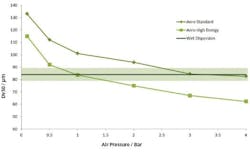
These data suggest that it would be possible to use either of the venturi tested. However, by plotting particle size as a function of air pressure for each venturi (Figure 5) it can be seen that the standard venturi is the better option. This plot shows that the MODR is larger with the standard venturi than with the high energy disperser.
These results show that with the high energy disperser any variation in air pressure will have a significant effect on particle size, compromising the ability of the method to meet the ATP. Using the standard venturi, on the other hand, the particle size results are reasonably consistent across the pressure range 3 to 4 bar. This venturi will therefore deliver an inherently more robust measurement. The MODR associated with its use can be determined, in terms of suitable air pressure, on the basis of these data.
Plotting measured particle size as a function of air pressure for each venturi disperser. Shaded region shows where the results are in agreement with the reference method to within USP 429 guidance. The standard venturi disperser delivers a wider MODR.
METHOD VALIDATION
The data shown in Figure 5 enable the selection of a dispersion pressure which would be expected to deliver robust results. To ensure that a proposed method meets the ATP, it is essential to verify that any variability in the way the method is applied does not shift the precision of the results outside the intended limits. This requires the method to be validated, following the guidance outlined in ICH Q2.
Two concepts are central to confirming that a particle sizing method is fit for purpose: repeatability and reproducibility. Assessing repeatability involves duplicate measurements of the same sample. It therefore tests the precision of the instrument, and the consistency of the sampling and dispersion process. Reproducibility is a broader concept that also encompasses multiple operators or even multiple analytical system installations.
Both the USP [2] and EP [3] recommend acceptance criteria for reproducibility testing. A Coefficient of Variability (COV) of less that 10% is suggested as acceptable for the median (Dv50) particle size or any similar value which is close to the center of the particle size distribution. This figure rises to 15% on values towards the edge of the distribution, such as Dv10 and Dv90, the particle size below which 10 and 90% of the population lies on the basis of volume. These limits are doubled for samples containing particles smaller than 10 microns because of the difficulties associated with dispersing such fine powders.
In our example then, where the acceptance criteria for the results are based on pharmacopoeial guidance, robust definition of the MODR requires that any source of variability does not take data reproducibility outside these limits. For example, the precision of air pressure control during dispersion is a function of the analyzer. If air pressure, a CQA, is controlled to within +/-0.1 bar, it is necessary to conduct experiments to determine the level of variability that this introduces in terms of the repeatability and reproducibility of the measured data. All potential sources of variability must be investigated in this way.
TOOLS TO EASE AQBD
As with QbD, AQbD places the emphasis on fully understanding a process, rather than simply focusing on a set of conditions that work for certain sample types. The potential rewards of this approach have already been highlighted, but gaining the necessary understanding is inextricably linked with more extensive experimentation. Tools that can alleviate the burden associated with this research are therefore to be welcomed.
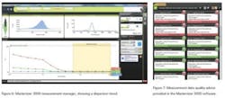
Figure 6 shows a screen shot from the Mastersizer 3000 illustrating the Measurement Manager tool. This is a software feature that provides real-time feedback which indicates the impact of changing an analytical parameter. Parameters can either be modified by the user in real-time as part of a manually controlled measurement or they can be set within pre-defined measurement sequences within the software’s SOP-player tool. This tool provides the first step towards full automation of the method development process.
In addition to aiding with the process of method development, there is also a requirement to ensure that the data collected are reasonable and therefore reflect the capabilities of the analytical technique in terms of both resolving product changes and delivering reproducible results. Here, tools to assess the quality of the data are extremely valuable, helping to guide the user towards the definition of a good method.
Figure 7 shows the output of the Data Quality assessment tool provided in the Mastersizer 3000. Advice is given relating the measurement process (e.g. instrument cleanliness and alignment) and also the analysis process (e.g. the goodness of fit between the light scattering data acquired by the instrument and the optical model selected to calculate a size distribution from these data). This helps to address many of the method control issues highlighted in Figure 4. Software advances such as these can therefore make a big difference when it comes to the application of AQbD, and they substantially ease the analytical burden associated with its implementation.
LOOKING AHEAD
A decade or so ago the introduction of standard operating procedures (SOPs) was groundbreaking, but analytical method development is now moving beyond simply defining a fixed set of measurement parameters. AQbD invites analysts to establish a robust MODR, a safe analytical working space. Working within the MODR ensures that results consistently meet defined quality criteria while at the same time providing the flexibility to respond to routinely encountered variability. The understanding that comes with scoping the MODR secures robust application of an analytical method across the product lifecycle and substantially eases method transfer.
As with QbD, AQbD holds out the attraction of greater understanding, but brings with it the burden of a broader research remit. However, advances in instrumentation, most especially in software, can make a major contribution when it comes to efficient scoping of the MODR. Features such as real-time feedback on the stability of a measurement and the impact of changes, for example, and the ability to automatically step through a series of SOPs, can help to substantially lighten the analytical burden, enabling analysts to reap the benefits of AQbD more easily.
References
[1] QbD Considerations for Analytical Methods – FDA Perspective. Presentation by SharmistaChatterjee at IFPAC Annual Meeting, Jan 25th 2013. Available for download
[2] General Chapter <429>, “Light Diffraction Measurement Of Particle Size”, United States Pharmacopeia, Pharmacopoeial Forum (2005), 31, pp1235-1241

