An Integrated Approach to Buffer Dilution and Storage
Editor’s Note: Please click here for this team’s description of the use of guided wave radar (GWR) for non-invasive volume measurement in disposable bioprocess bags.
Most processing solutions in bioprocess manufacturing are very dilute. Consequently, these solutions can be prepared and stored as concentrates, thereby significantly reducing storage volume requirements. The concentrated solutions can then be accurately diluted, inline, with water and sent directly to processing steps such as chromatography or tangential flow filtration.
This strategy, inline dilution, has great potential to reduce capital expenditure of a biopharmaceutical manufacturing facility by minimizing the size and number of preparation and storage vessels. In addition, a reduction of processing solution volume allows greater implementation of single-use bioprocess bags in place of traditional stainless steel or higher alloy tanks, further reducing capital expenses. The use of disposables also eliminates the need for cleaning and steaming in between runs, while disposable bags are corrosion-resistant to chloride-containing buffers.
A bag volume limitation of approximately 2,500 L has been a hurdle for implementing buffer storage bags in very large-scale biologics manufacturing facilities1. However, using buffers concentrated by factors of 10x and greater, we have been able to extend the use of bioprocess bags to even our largest antibody manufacturing facilities.
This manuscript will discuss how Genentech developed and tested inline dilution technology for implementation in a new large-scale antibody manufacturing facility. We will also discuss the integration of disposable bag technology to the inline dilution systems. The combination of these two technologies has resulted in significant capital reduction and some operating cost advantage by using bags instead of tanks.
The Challenge
The biotechnology industry has matured quickly and the demand for biological therapeutics, particularly antibodies, has increased markedly over the past 10 years. In response to the higher production demands, biopharmaceutical manufacturing facilities have been challenged to increase protein expression titers and/or increase bioreactor production volumes. Batches exceeding 100 kg of protein are becoming more common as annual demand for antibody biologics can approach several metric tons.
As protein batch sizes increase, downstream processing buffer equipment sizes must also increase. Simply scaling up equipment size, particularly buffer preparation and storage tanks, can significantly impact capital expenditure for a new facility. Genentech was recently faced with this challenge during the construction of a new 25,000-liter bioreactor-scale antibody manufacturing facility. This led us to develop, test, and implement inline dilution systems for chromatography operations in the antibody purification train, thus reducing the size of many buffer preparation and storage vessels. We conservatively targeted buffer concentration factors up to 10x, which allowed us to reduce the size of many vessels to ≤ 2500 L and thereby use disposable bioprocess bags instead of stainless steel or higher alloy tanks.
Inline dilution is relatively simple in concept: it is the simultaneous mixing of a concentrated solution and water (or some other diluent) inside a processing line to produce a normal strength, process-ready solution. Inline dilution applications in the biopharmaceutical industry present unique challenges because the processing solutions, such as chemical buffers, often must fall within very tight specification ranges for pH, conductivity, osmolality, and temperature, which can be critical process parameters. This requires that a precise mixture of the concentrated solution and water be delivered with minimal deviation over time. Also, the solution must be well mixed prior to delivery onto a chromatography column or tangential flow filtration (TFF) system. Failure to meet precise targets could adversely impact process performance, and/or process parameters could fall outside of the validated ranges, causing a batch deviation.
Buffer Solubility Studies
Our main target application for inline dilution was chromatography buffers, so we first sought to determine the solubility limits of 30 unique processing buffer solutions. Knowledge of these limits provided our first glimpse of the potential for tank size reduction and capital savings in our future facility.
The solubility experiments were performed as follows (the results are shown in Table 1):
- The chemicals for each specific buffer were carefully weighed and added to a 250-mL glass beaker with stir bar. A precise volume of water was added to the beaker and aggressively mixed with a stir bar at room temperature (approximately 19°C) for 30 minutes. Visual observations were made to determine if the chemicals had fully dissolved.
- If not fully dissolved, additional water was added after each 30-minute increment. This process was repeated until the chemicals fully dissolved. The solubility limit was noted.
- On this first-pass study, we wanted to gather a limited set of solution physical properties such as density and viscosity to see if any particularly difficult solutions would be encountered. Temperature was measured with a VWR digital thermometer (± 1°C accuracy) and pH was measured with a benchtop pH meter. Density was measured at room temperature by weighing a 1.0-mL sample taken by a calibrated pipette and weighed on a calibrated Mettler Toledo scale. Viscosity was measured at room temperature using a Cannon-Fenske viscometer.
The results of the solubility studies were very encouraging and theoretically proved that we could reduce buffer preparation and buffer hold tank size substantially in a number of chromatography steps (Table 1). Since this study only addressed solubility limits, we had other potential challenges to address such as the filterability characteristics of the buffer concentrates and stability over time. Plus, we had to determine new pH and conductivity specifications for the preparation of concentrated buffers. These are time consuming but essential lab studies to complete. Ultimately, we decided to limit the concentration factor of chromatography buffers in our new facility to 10x, which is conservative for most of the buffers used. However, reducing tank size 10x would significantly reduce capital expenses and would still provide flexibility to concentrate further if additional capacity was needed in the future.
This is one of the underlying benefits of using concentrated buffers. Unless the solubility limit is approached, it is easy to scale up buffer capacity by simply increasing the concentration and re-programming the dilution skid. We settled on a conservative 10x concentration factor because we wanted to gather real-world experience before aggressively concentrating the buffers since that puts more challenge on the blend precision required.
Construction of a Prototype Inline Dilution System
Now that we had supporting solubility data, our challenge was to establish proof of concept for inline dilution at near-manufacturing-scale. With Biokinetics (Emeryville, Calif.) we designed and built a custom automated inline dilution system capable of multi-component blends, which we called the “prototype system.” Our design strategy was to equip the system with extremely accurate and precise pumps, valves (Baumann), and inline flow meters that could reliably control the flow rate of both water and the concentrated buffer solutions. If we could guarantee precise flow control over an acceptable range, we felt confident that inline dilution would be a success at our new facility5.
| Unit Op |
Buffer Description | Volume (L) | MAX Conc Factor |
Conc. Volume (L) |
| Affinity Chrom |
Equil+Wash1&3 | 36774 |
25 | 735 |
| Wash 2 | 12700 | 4.8 | 1323 | |
| Elution |
10676 | 70 | 76 | |
| Regen buffer |
11850 | 150 | 40 | |
| Storage |
1976 | 2 | 494 | |
| Skid Storage |
190 | |||
| CEX Chrom |
Equil 1 / Wash | 5776 | 100 | 29 |
| Elution |
4560 | 30 | 76 | |
| Sanitization |
3466 | 38 | 46 | |
| Storage |
3466 | 190 | 9 | |
| AEX Chrom |
Equil2 | 6936 | 50 | 69 |
| Sanitization |
2310 | 38 | 30 | |
| Storage |
2310 | 190 | 6 | |
| UF-DF |
Diafiltration | 16250 | 50 | 163 |
| Conditioning |
162.6 | 1 | 81 | |
| Storage |
5850 | 190 | 15 | |
| Regen |
1000 | 133 | 4 | |
| Long-Term Storage |
1710 | 20 | 43 | |
| Table 1. Antibody buffer concentration data at the 25,000-liter reactor scale | ||||
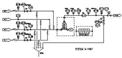
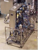
The prototype system was capable of a total blend flow rate of 40 L/min. A schematic and picture of the prototype inline dilution system are shown in Figures 1 and 2.
(Click to enlarge image) Figure 1.
Figure 2.
The system was designed so that either a rotary lobe positive displacement pump (Viking DuraLobe) or centrifugal pump could be connected to the inlet of any of the four inlet lines. The pumps were used to drive liquid through the system and multiple pumps could operate simultaneously to create multi-component blends, a function required for performing gradients with concentrates. Flow rate was controlled by direct feedback from Coriolis mass flow meters (Endress + Hauser or MicroMotion) on each individual line to either the rotary lobe pump or valve.
The valve could also be used to control backpressure in the line as the rotary lobe pump simultaneously controlled flow rate. This helps to make “pump slip” less of a problem. Pumping into higher pressure makes PD pumps perform more consistently and over a wider dynamic range. If the centrifugal pump was used, the valve controlled flow rate while the pump supplied constant high-pressure flow at 50-80 psig. Various flow control strategies were tested to determine the best option, which is discussed below. The system was also equipped with a filter housing, a divert-to-drain line, and analytical instruments for pH, conductivity, and optical density measurements.
Lessons Learned from the Prototype System
The testing team chose to use volumetric flow rate as the primary means of control and intentionally avoided using secondary feedback control on parameters such as pH or conductivity even though our buffer specifications are ultimately based on pH and conductivity. This choice was made primarily because flow rate, measured by a Coriolis mass flow meter, is the most accurate inline measurement that can be made. Inline pH and conductivity meters have an inherent tendency to drift and improper calibration could result in false readings. Ultimately, we trusted that the mass flow meters were the most accurate and reliable option, and the results from our tests with the prototype system supported this. This strategy does put a heavier burden on buffer prep operations. To reduce propagation of error, the prepared concentrate must be very close to target setpoints so it is recommended that off-line measurements are considered if this results in more accurate measurements.
We relied on an inline filter housing to provide the necessary mixing environment for the blended streams. These sterile filter housings are already part of our standard skid design so they introduced no additional complexity. Inline static mixers were also tested but provided virtually no additional benefit. The filter housing (with or without filter installed) served as a “well-mixed” chamber and smoothed out the pH and conductivity profiles of blended solutions. We positioned pH and conductivity sensors downstream of the housing so that the sensors would see very little oscillation when we recorded measurements. This configuration worked extremely well for the prototype system and was incorporated in all future designs.
The prototype system was equipped with a divert line located just upstream of the outlet to the system. The purpose of the divert line was to direct the blended flow to drain until it was within specification. At that point, flow would transition away from the divert line and into a chromatography column or other processing step. It is important that this transition occurs with minimal pressure disturbance or the blend ratio will temporarily be thrown out-of -specification due to a pressure spike or dip. Therefore, the divert line had a backpressure control valve that throttled to match the pressure of the chromatography column at a specific flow rate, minimizing the differential pressure during the transition. Our testing showed that some pressure change is inevitable and the user must strive to optimize the flow-control tuning constants and the timing of any discrete valves on the divert and system outlet lines to minimize the effect of this inevitable pressure disturbance.
Most of the inline dilution testing on the prototype skid was not performed with actual process buffers. Instead, we used concentrated acetone solutions to mimic concentrated buffers. This enabled the use of an inline optical density meter to measure UV light absorbance of the blend at 280 nm. Inline optical density is much more accurate than inline pH or conductivity and allowed us to perform more reliable blend accuracy studies on the system. We highly recommend this technique for those testing inline dilution systems. Early attempts were made using a flow-through conductivity device but temperature effects, electrical noise, and lack of a good dynamic range led us to quickly abandon this approach.
Design and Testing of a Manufacturing Inline Dilution System
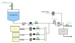
Results and testing from the prototype system helped tailor the design of three large-scale inline dilution systems for our new manufacturing facility. Prior to delivery into the new plant, we brought one of the systems into our pilot plant facility in South San Francisco for performance testing. This allowed time to test the mechanical and automation features of the inline dilution system and make changes if required. The testing also provided insight into how the system would perform during actual operation in the plant. A simplified schematic of the manufacturing inline dilution system is shown in Figure 3.
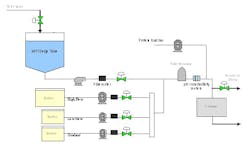
The system has three buffer feed lines (one capable of higher flow rate) and a water line with surge tank upstream of the pump. The surge tank provided a link between the high-pressure WFI supply loop and the inline dilution system, which created an “air break” between the two systems. It is an internal regulatory requirement to avoid connecting process systems directly to WFI systems without an air break. The break tank also serves to dampen pressure fluctuations that may occur in the WFI loop, for instance when another tank begins or ends a CIP cycle, and it allows time to respond to any sort of extreme situation such as the WFI supply being cut off. A divert line with pneumatic control valve was located just upstream of the chromatography column. There was also a separate “load line” used to transfer the initial protein pool onto the column. By segregating the load line from the buffer lines, we minimized the dilution-effect of our protein product that would occur within the buffer line and filter housing. The load and buffer lines were each equipped with a rotary lobe pump and the WFI line was equipped with a centrifugal pump. For simplicity, the discrete valves are not shown on the schematic.
(Click to enlarge image) Figure 3.
We focused on four areas during testing of the manufacturing system:
- Blend accuracy
- Impact of pressure disturbances
- Gradient formation (for chromatography operations)
- Testing multi-step sequences
Most testing was performed at blend ratios of 10x since this was the highest concentrate factor proposed for our new facility.
Blend Accuracy and Precision:
The accuracy of blended solutions produced by the inline dilution system was quantified by comparing to precise hand-made dilutions. We produced 10x blends on the skid using a concentrated acetone solution and purified water, meaning that the flow rate of acetone solution was 10% of the combined flow rate and water was 90%. Samples were taken from the outlet of the inline dilution system and the optical density (A280-A320) was measured on a benchtop UV meter. Using a sensitive benchtop scale and a volumetric flask, 100mL of concentrated acetone solution was combined with 900mL of purified water to create the hand dilutions. The optical densities of these samples were measured and average values are shown in Table 2. Blends from the inline dilution system differed by only 0.6%-1.2% from the hand dilutions. These results gave us confidence that 10x concentrates could be used in our new facility.
| Test #1 | Test #2 | |
| Sample | Optical Density A280-320 |
Optical Density A280-320 |
| 0.1% acetone- hand dilution |
0.167 (N=4) | 0.171 (N=5) |
| 0.1% acetone- LHS skid dilution- 20 LPM | 0.168 (N=6) |
0.172 (N=6) |
| 0.1% acetone- LHS skid dilution- 60 LPM |
0.168 (N=6) | 0.173 (N=6) |
| 1% acetone- from tank | 1.69 (N=2) | 1.70 (N=2) |
| Table 2. |
||
Impact of Pressure Disturbances:
During the transition of flow from divert to process or vice-versa, a pressure disturbance is generated due to inherent pressure differences between the two lines and from the timing of discrete valves on those lines. The sudden change in pressure will impact the flow rates of solutions controlled by the pumps and valves in each line. For example, if the pressure suddenly drops, the resistance to flow will also drop and the flow rate will increase.
Adjusting the proportional-integral-derivative (PID) tuning parameters for each pump and valve can significantly affect the time required to respond to a pressure disturbance. If flow rates are out of specification for an extended period of time, the blend ratio will be impacted and any buffers produced may also be out of specification. This can lead to significant buffer wastage and prevent successful transitions between the divert and process lines. Our goal was to optimize the tuning parameters for each pump and valve to respond quickly to pressure disturbances without compromising flow rate stability. We also tested the various flow control strategies to identify the most robust option.
The diagram in Figure 4 shows the setup used to generate artificial pressure disturbances on the inline dilution system. By toggling automated discrete valves on the divert and process lines, we could redirect flow between the two lines. Back-pressure was controlled through manipulation of a pneumatic valve on the divert line and a hand valve on the process line. By creating a pressure differential between the two lines at any given flow rate, a pressure disturbance was created once the flow transition took place. We quantified the effects of pressure disturbances on 10x blends (acetone solution and water) by measuring OD downstream of the filter housing. We leveraged this to tune our flow control pumps and valves by observing the response to pressure disturbances. We adjusted the proportional (P) and integral (I) tuning parameters to minimize the pressure disturbance effect while still maintaining flow stability. The derivative (D) constant was not changed.
(Click to enlarge image) Figure 4.
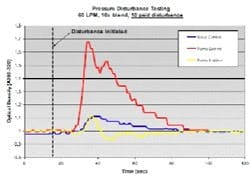
Figure 5 shows data from a 10 psid pressure disturbance test on a 10x blend with 60 LPM total flow. We examined three control strategies: 1) valve controls flow; pump at fixed speed; 2) pump controls flow; valve at fixed position; and 3) pump controls flow; valve controls backpressure in the line. The pumps and valves were well-tuned in each case. The data shows that pump control alone is not very responsive to pressure disturbances compared to other control options. We saw a 70% change in the blend ratio using pump control compared to only 10% for valve control and pump/valve control.
(Click to enlarge image) Figure 5.
We highly recommend incorporating control valves on all buffer lines in the design of an inline dilution system. This will enable more robust and sophisticated flow control strategies and provide flexibility to maximize buffer concentration factors to 10x and possibly greater.
Chromatography Gradients and Multi-step Sequences:
One requirement for the inline dilution systems in our new facility was the ability to produce gradients with concentrated buffers. A chromatography gradient involves a linear change in either conductivity or pH at constant total flow rate. To produce this type of a gradient, the inline dilution skid must be capable of blending three streams simultaneously (tertiary blend). One stream is water and the other two are concentrated buffers. The pumps, valves, and flow meters on the concentrated buffer lines must have an adequate turndown ratio to accommodate the relatively low concentrate flow seen at the beginning or end of the gradient. Flow stability at these low flow rates is critical.
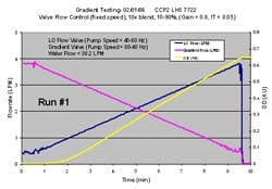
Figure 6 shows a successful gradient that we produced on the inline dilution system. The two flow rates in the plot represent 10x concentrated buffers, while the water flow rate is not shown. While there was slight flow instability at the lowest flow rates, as seen by the oscillations on the trend, this was acceptable because it did not impact the resulting final blend as seen by the yellow OD trend, which was smooth and linear, mainly because the 25 liter filter housing chamber effectively mixed the oscillations completely. We were very pleased with these results and felt comfortable implementing gradients with concentrated buffers at our new facility.
(Click to enlarge image) Figure 6.
Multi-step Sequences:
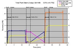
Using TotalPlant Batch software from Honeywell, we were able to string together multiple chromatography phases to test multi-step sequences on our inline dilution system-steps that were fully representative of an actual chromatography operation. The plot in Figure 7 depicts a three-step sequence. Again, the “concentrated buffers” were acetone solutions and the water flow rate, which is constant for each step, is not shown.
Step 1- binary blend with 10x concentrate and water
Step 2- tertiary (3 stream) blend gradient with 10x concentrates and water
Step 3- binary blend with 4x concentrate and water
The gaps between the dashed lines show the time required to transition from one blend to another. During this time, the buffer is “out of specification” and is diverted to drain. Once the buffer has reached its target, the flow is transitioned through the process line and directed to the chromatography column. The “divert time” is a function of the total flow rate and size of the filter housing, since the housing must be completely flushed to establish a new blend ratio. One general rule of thumb is that it takes three filter housing volumes worth of liquid to achieve 95% removal of the previous solution.
(Click to enlarge image) Figure 7.
Inline Dilution and Disposable Bags in Our New Facility
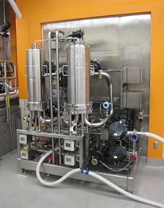
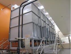
Satisfied with the performance of the inline dilution systems tested, we gave the final thumbs up to approve installation of three inline dilution systems for chromatography operations in our new facility (see one of the installed systems in Figure 8). Each system is capable of blending 10x concentrates with potentially higher concentrations in the future. The inline dilution systems were coupled to a large-scale disposable bag system that housed 12 2500-L bag holders (fabricated by ConeCraft; Figure 9) used primarily for buffer hold operations.
Capital equipment costs represent a large percentage of the cost of a new biomanufacturing facility6 so the capital savings from this setup were tremendous. Instead of purchasing 12 Hastelloy tanks up to 25,000L in size, we were able to construct a very compact bag holder system. A reduction in buffer prep tank size led to further capital savings. Use of disposable bags, especially for buffer storage, is widespread in the biopharmaceutical industry7 and we felt comfortable using bags at such a large scale.
The use of disposable bag technology will provide process efficiencies during production by eliminating clean-in-place (CIP) and steam-in-place (SIP) operations plus reduce the water for injection (WFI) used in the facility1. Reducing WFI demand reduced the size and utility requirements for the WFI production system in the facility. Coupled with a reduction in the number and size of chemical storage tanks, we saw further capital savings as a direct result of implementing inline dilution.
Summary and Recommendations
Through this extensive engineering project, we confirmed our belief that inline dilution could be a valuable tool for chromatography operations in a large-scale biomanufacturing facility. We showed that an inline dilution system equipped with precise pumps, valves, and flow meters could produce extremely accurate 10x blends at large scale, including gradients where the concentration is changing linearly over time. We determined that inline control of pH and conductivity is not necessary to guarantee accurate blends since tracking flow rate through a Coriolis mass flow meter is inherently more accurate. Careful tuning of the flow control parameters is vitally important to minimizing the effects of pressure disturbances on the system.
Also, the type of flow control strategy implemented will impact the magnitude of a disturbance effect. In our studies, flow control by the positive displacement pump alone was not sufficient. Instead, we recommend controlling flow by an inline pneumatic or electric diaphragm valve or by simultaneous control of the pump and valve to control flow rate and backpressure, respectively. One other important aspect of our inline dilution system design was the use of a filter housing as the mixing chamber for the blended buffers. The housing was positioned upstream of the inline analytical instruments, such as pH and conductivity meters, and served a dual function of both mixing and filtering the buffers prior to delivery onto the chromatography column.
The capital savings from implementing inline dilution at our large-scale facility were tremendous. We were able to significantly reduce the size of buffer prep tanks, we replaced many buffer hold tanks with disposable bag containers, and also reduced the WFI and CIP chemical requirements for the facility. In the future, we could further increase the capacity of our facility by concentrating buffers greater than 10x8. We will also consider inline dilution applications for other unit operations such as media prep and tangential flow filtration (TFF). Inline dilution may provide additional benefits for renovation of our existing biomanufacturing facilities to increase capacity. Using bags together with inline dilution makes such renovation less complicated and more cost-effective.
About the Authors
Tim Matthews is a Senior Engineer and group leader in Process Development Engineering at Genentech. He has a B.S. in Chemical Engineering with a Minor in Environmental Engineering from Penn State University. Please address correspondence to [email protected].
Bryan Bean is currently working in Manufacturing Sciences supporting commercial bacterial fermentation operations at Genentech. He has worked in the Process Development Engineering group at Genentech from 2004 to 2008 with a focus on testing and implementing novel bioprocessing technologies. Bryan has a B.S. in Chemical Engineering from the University of Washington.
Poonam Mulherkar is a Senior Engineer in Manufacturing Sciences, Vacaville. She has 12 years of experience in various aspects of Process Development, Technology Transfer and Facility Startup. She has an M.S. in Chemical Engineering from the University of Cincinnati.
Bradley Wolk is a Distinguished Engineer and Director of Pharmaceutical and Packaging Engineering at Genentech. He joined the company in 1991 and has been active in facility and equipment design, process and technology development, and technical collaborations in the areas of cell culture, purification, filling and material sciences. He has a B.S. in Chemical Engineering from U.C. Davis.
References:
1 Monge, Miriam; Preusting, Hans; Kuyvenhoven, Hans. Disposable technology for biopharmaceutical manufacturing. World Pharmaceutical Developments. 2001, 2, 126-128.
2 Kelley, Brian. Very Large Scale Monoclonal Antibody Purification: The Case for Conventional Unit Operations. Biotechnol. Prog. 2007, 23, 995-1008.
3 Fahrner, Robert L.; Knudsen, Heather L.; Basey, Carol D.; Galan, Walter; Feuerhelm, Dian; Vanderlaan, Martin; Blank, Gregory S. Industrial Purification of Pharmaceutical Antibodies: Development, Operation, and Validation of Chromatography Processes. Biotechnology and Genetic Engineering Review. 2001, 18, 301-327.
4 Farid, Suzanne S. Process economics of industrial monoclonal antibody manufacture. Journal of Chromatography. 2007. vol 848, issue 1, 8-18.
5 Greenwald, Roy; Rochelle, Bill. Large-scale chromatography becoming state-of-the-art. Pharmaceutical Engineering. 2006, 26, 2.
6 The shrinking biomanufacturing facility. Genetic Engineering & Biotechnology News. 2005. 25, 19.
7 Sinclair, Andrew. The disposables revolution- the use of disposables has changed significantly in the biopharmaceutical industry. Biopharm International 2008.
8 Bellafiore, Lou. In line buffer dilution: the “killer app” for process analytical technology. Bioprocess International. 2007.
