Maintaining Integrity: Effects of SIP Sterilization on PTFE Valve Diaphragms
Steam-in-place (SIP) sterilization is an essential process in the pharmaceutical and biotechnology industries. The American Society of Mechanical Engineers Bioprocessing Equipment (ASME-BPE) standard recommends diaphragm valves for aseptic and sterile systems. Weir-type sanitary valves with polytetrafluoroethylene (PTFE) diaphragms are most commonly used in these systems, but sanitary diverter valves and valves with hermetic PTFE diaphragm stem seals are also used extensively.
Typical SIP cycle temperature parameters are 120°C to 135°C at corresponding saturated steam pressure, with exposure time dependent on system design and complexity [1]. The ASME-BPE 2009 Standard Appendix J for simulated SIP cycle parameters calls for minimum 130°C steam and one hour exposure [2]. Overkill SIP parameters are minimum 140°C steam for two to four hours exposure. These SIP cycles are cooled slowly with pressurized clean air.
To achieve more frequent batch changes and greater production yields, some in the pharmaceutical industry have begun to use high-temperature, short-time (HTST) sterilization systems with SIP temperatures ranging from 140°C to 160°C [3]. These SIP cycles are cooled more quickly with air or water, often resulting in blistering of PTFE diaphragms, posing sterility problems if not detected early enough and reducing their service lives.
Recently, we did our own experimentation to investigate this phenomenon. This article will discuss the types of valves and diaphragms tested, the test equipment and procedures used, analysis of blistered PTFE diaphragms, the mechanics of blister formation, and what can be done to alleviate it.
Diaphragm Variability
Modern pharmaceutical and bioprocessing plants have large aseptic systems of vessels, fermentors and bioreactors interconnected by a maze of piping. Integral to these systems are diaphragm valves, which the ASME-BPE standard recommends for pharmaceutical and bioprocessing applications with product contact [2]. The types of diaphragm valves recommended are weir-type, diverting and other two-piece stem and plug valves with diaphragm stem seals.
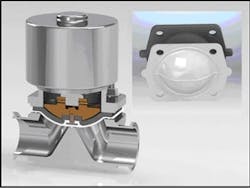
The most commonly used diaphragm valves are weir-type (Figure 1). These valves provide the self-draining capability required for hygienic processing. Usually made of 316L stainless steel, the valves are supplied with either manual or automated actuators.
The heart of a weir valve is the PTFE diaphragm. As shown in Figure 1, the two-piece diaphragms consist of a PTFE face layer and EPDM elastomer backing, which provides resiliency and compression during valve actuation. Having no center hole, the PTFE diaphragm isolates the product from the valve stem and actuator mechanism. PTFE diaphragms are used in critical, high-temperature SIP applications and with harsh chemicals.
PTFE polymers are known for their high purity, exceptional non-adhering properties, chemical resistance, and temperature capabilities up to 260°C. These polymers have ultra-low-level extractables, conforming to FDA 21 CFR 177.1550 and USP28 Class VI Part 87 and 88. Chemically, biochemically, and enzymatically inert, they have wide acceptance in pharmaceutical and biotechnology industries.
PTFE polymers are grouped into two types: conventional, which are white in appearance, and modified, which are more translucent. Containing up to one percent perfluoropropyl vinyl ether (PPVE), modified PTFE compounds represent the next generation of PTFE polymers, available in a number of different grades. Compression molded parts of modified PTFE have a lower percentage of voids and lower permeation rates for liquid and vapor chemicals and helium gas. Modified PTFE diaphragm disks typically offer a 30% reduction in permeability for different chemicals [4].
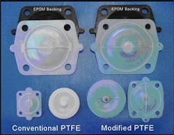
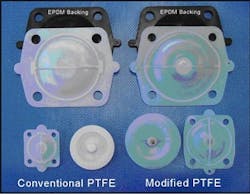
Pictured in Figure 2 are conventional and modified PTFE diaphragms for weir-type valves. The diaphragms are manufactured by compression-molding powder resin, followed by sintering. The threaded drive stud in the center is usually a molded-in metal bolt or machined from PTFE stock, as seen in the round conventional PTFE diaphragm. Some valve manufacturers mold their own diaphragms, while others purchase them from distributors. Pharmaceutical and bioprocessing facilities also purchase replacement diaphragms based on published dimensional specifications, service temperature ratings, and certification of conformance to applicable FDA and USP regulations. Distributors publish maximum intermittent steam temperatures or SIP sterilization capabilities up to 165°C for PTFE/EPDM diaphragms.
Differences in production processes and grades result in PTFE diaphragms with different performance properties and durability. PTFE diaphragms manufactured by some processes cannot withstand high-temperature applications or meet the demands of SIP sterilization.
Diaphragm Integrity and Performance
SIP cycles consist of three stages—heat-up, hold/exposure and cool-down. During the heat-up stage, saturated steam is injected, and the equipment with valves is heated to the required sterilization temperature. This stage is complete when the cold spot in the system—usually the condensate drain, dead leg, tank bottom, or furthest location from steam inlet—reaches the pre-set sterilization temperature. When a thermocouple probe at the slowest heating location reaches this temperature, the hold or exposure stage begins, during which both pressure and temperature must be accurately controlled. Exposure time is typically 30 to 45 minutes at 20 to 30 psi with corresponding steam temperatures of 121°C to 135°C [5]. For systems with hard-to-access areas, exposure times will be longer.
Because older SIP systems currently in use are not automated, exposure times will be longer, as manual checks and temperature mapping are performed by operators [6]. In overkill SIP cycles for large industrial fermentation systems with complex feed-system piping, steam temperature of 150°C and exposure times of four hours are needed to insure sterility [7]. The extended exposure times are known to have adverse effects on elastomeric tubing, gaskets, hoses and other polymeric materials and components [8]. The new trend of HTST sterilization shortens the hold time but exposes the equipment and diaphragms to temperatures of 140°C to 160°C [5]. As noted, high-temperature SIP cycles, typically with fast air or water cooling, also adversely affect PTFE diaphragms.
After SIP sterilization, the system is cooled down to ambient temperature and atmospheric pressure. Different aseptic systems are cooled down at different rates. Cooling with air can be fast or slow, depending upon air pressure, flow rate and complexity of the aseptic system. In a typical SIP system, air cooling takes about an hour. Cold water flush lowers the system temperature more rapidly, which is extremely damaging to the PTFE diaphragms.
During an SIP sterilization cycle, not all of the valves in a system are heated and cooled at the same time. This means that the PTFE diaphragms will be exposed to different SIP conditions impacting their integrity and performance. Valves near the cold spot will heat up and cool at slower rates.
Valves upstream and close to the steam inlet will heat up much more quickly, subjecting the PTFE diaphragms to longer, higher temperature steam exposure. Valves in large and complex systems have similar issues during the cool-down process. Upstream valves will cool down at a faster rate which is extremely detrimental to PTFE diaphragms.
SIP sterilization of large, complex systems is further complicated by uninsulated equipment and piping, which result in heat loss and temperature nonuniformities. To compensate for radiant heat losses, system operators use higher steam pressures and longer SIP cycles [9].
At the beginning of an SIP cycle, the sudden injection of steam at high velocity and pressure reduction will expand into vessels, valves and piping systems, creating a superheated steam condition [10-14]. This condition is to be avoided, since superheated steam does not conform to fixed temperature-pressure relationships; nor does it have the same “kill” kinetics for micro-organisms and spores. A clear, colorless gas, superheated steam has a greater permeability effect on PTFE diaphragms, particularly those upstream near the site of steam injection in HTST SIP cycles. It is also known to cause failure of hoses and other polymeric components.
Increased product throughput and frequent batch changes are subjecting PTFE diaphragms to greater frequency and higher temperature SIP sterilization with fast cooling. As a result, diaphragm failures, including bead deformation, leakage, and obstruction of flow due to diaphragm warpage and distortion, are becoming more frequent. And recently there also have been reports of diaphragm blistering, in which crevices and other surface anomalies form, putting at risk the sterility of aseptic systems.
Blistering in PTFE Diaphragms
A number of field cases of PTFE diaphragm blistering have been reported after SIP sterilization. The diaphragms were used in sanitary systems in pharmaceutical/bioprocessing, food and dairy facilities. The blistered diaphragms were provided by the valve manufacturers after they were returned by end-users. Following are three examples of PTFE diaphragms that developed blisters during SIP sterilization at higher than typical temperatures.
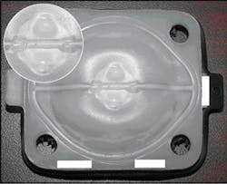
Case 1: Figure 3 shows a blistered DIN 20 weir-type PTFE diaphragm that was SIP sterilized at 150°C. The blisters were discovered during a scheduled maintenance interval, and when pierced expelled a clear, water-like liquid. The PTFE diaphragm also sustained external bead deformation, flex fatigue stresses and permeation damage, as evidenced by the cloudy discolorations.
Case 2: The PTFE valve diaphragm underwent ~140°C high-temperature SIP once a day, and was cleaned in place with caustic soda and nitric acid. Again blisters containing a clear liquid were detected during system maintenance. The blisters were the same in appearance as the blisters in Figure 3. Analyzed with Fourier transform infrared (FTIR) spectroscopy, the liquid was a near match with distilled water, and its moderately acidic ~3 pH was consistent with the nitric acid cleaning.
Case 3: Sanitary valves with PTFE diaphragms were SIP sterilized once a day at 145°C with exposure time of 20 minutes, and cooled down with a water quench. The valves underwent total of 50,000 actuations and ~400 SIP cycles, after which blisters with the same appearance and morphology as those in Case 1 were discovered during system maintenance. These blisters also contained clear liquid.
Testing to Replicate Blistering
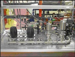
To investigate the effects of SIP sterilization on PTFE valve diaphragms, laboratory equipment was designed and built to test standard DIN 50 (2") weir-type valves with automatic actuators and assembled with sanitary stainless steel piping with tri-clamp connections (Figure 4). The test equipment was connected to industrial saturated stem for SIP, clean potable water for cooling, and plant air for purge. This equipment was fully interfaced with a PC control system for automated operation, data collection and SIP cycle control.
The fully automated and computer-integrated test equipment monitored and controlled steam temperature, pressure, and valve actuation, providing real time data display and collection. The system was also pre-programmed for automatic control and sequencing of SIP cycle heat-up, exposure and cool-down stages.
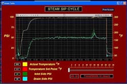
The SIP sterilization procedure was based on field Case 3 above. The valve was actuated by circulating clean water at 25°C/70 psi. After each 100 actuations, the valve was set to full open position and the PTFE diaphragm was SIP sterilized. SIP cycle parameters were 145°C/45 psi steam for 20 minutes exposure, followed by fast water quench cooling. The valve and PTFE diaphragm underwent a total of 40,000 actuations and 400 SIP cycles. The SIP parameters for heat-up, exposure and cool-down were automatically plotted for steam temperature and pressure, as shown in Figure 5.
Actual average SIP cycle parameters were 145°C (295 °F)/49 psi for 20 minutes. During the SIP cycle, the PTFE diaphragm was also subjected to steam conditions of 152°C (305°F)/60 psi for two minutes, due to a steam pressure spike caused by the pressure regulator. The plot also shows that the PTFE diaphragm was very rapidly cooled to ambient temperature with the cold water quench.
The valve was disassembled and the PTFE diaphragm was inspected after each 10,000 valve actuations and 100 SIP cycles. Small blisters were first noted during the initial inspection at 100 SIP cycles. During subsequent inspections at 200 and 300 cycles the blisters progressively increased in size and number. The final condition of the diaphragm after 400 SIP cycles is shown in Figure 6. Blisters formed on both the front and back, indicating permeation through the PTFE diaphragm. The blisters leaked small amounts of clear liquid when cut open for examination. In addition, the diaphragm again sustained external bead deformation, flex stresses and permeation damages. Steam permeation caused the EPDM backing diaphragm to soften, split and adhere to the PTFE diaphragm.
The inset photo in Figure 6 depicts internal morphology of the blisters taken with a high-power digital camera microscope. The photo clearly shows blistered expansions and crevices, which could harbor microbes and compromise sterility if they split open under continual operation.
Mechanics of Blister Formation
Liquids and gases will permeate PTFE to different extents depending upon pressure and temperature. Permeation involves molecular-level diffusion into PTFE, and is accelerated by an increase in temperature and pressure. Small molecule liquids and vapors will permeate PTFE more quickly than large molecules. Steam is a small-molecule permeant known to cause blisters in PTFE pipe liners during steam-cold water thermal cycling tests [15]. The PTFE-lined pipes withstand temperatures up to 260°C (500°F) and can be used in continuous steam up to 177°C (350°F) without adverse effects. However they should not be used in steam-cold water cycling due to stress-cracking and blistering [16]. PTFE components such as steal-braided hoses and tubes also can be used successfully in continuous steam applications up to 198°C (388°F), but again they are not recommended for steam-cold water cycling [17].
Blistering of PTFE diaphragms during SIP has largely caught the pharmaceutical and bioprocessing industries by surprise. Referenced literature sources are vague and do not provide clear explanations of this phenomenon. SIP sterilization produces a temperature and pressure gradient in the PTFE diaphragm, causing absorption of small amounts of steam vapor, which condenses within the diaphragm upon rapid cooling. When steam is reintroduced for the next SIP cycle, the entrapped water expands to vapor, forming micropores. In poorly manufactured PTFE diaphragms containing voids, steam vapor will also condense in these voids. Repeated pressure and thermal cycling expands these micropores and voids, ultimately forming water-filled blisters. These blister formations depend on SIP cycle frequency, exposure time, temperature, pressure of the saturated steam and the rate of cooling. During slow cooling, temperature and pressure decrease gradually allowing steam vapor to diffuse out of PTFE diaphragms. During rapid cooling, temperature and pressure decrease more quickly than the steam vapor can diffuse out of the part.
The new trend of high-temperature and high-pressure SIP cycles to achieve faster sterilization of cold spots in aseptic system are subjecting upstream PTFE diaphragms to more aggressive sterilization and cooling conditions. As a result, these diaphragms are more prone to failure from cracking, splitting, deformation and SIP steam-induced blisters.
Conclusions and Recommendations
SIP sterilization is critical to the operation of pharmaceutical and bioprocessing facilities. Demands for increased production, frequent batch changes, higher-temperature sterilization, and rapid cooling are causing diaphragm failures, including SIP-induced blisters that can compromise sterility if not detected and replaced early enough.
To avoid such failures, plant owners and operators can more precisely control SIP parameters, notably steam temperature and pressure. Equipment and piping systems can be thermally insulated to minimize heat losses and improve temperature uniformities during SIP cycles. Thermal insulation can also serve to lower steam temperature and pressure and reduce SIP cycle times by heating cold spots more efficiently.
In large, complex SIP systems, multiple steam inlets can be used to avoid high temperature/ pressure steam injection or lengthy overkill SIP cycles. Older manual SIP systems can be upgraded and computer integrated for SIP automation and efficient temperature mapping. In addition, computer-based thermal analysis tools can be used to minimize extreme hot and cold spots when designing process piping systems. SIP systems should also be designed and operated to avoid creating superheated steam conditions. Steam should be injected gradually to keep it in a saturated state. Steam pressure should not be reduced to below 50% or exceed reduction of 2:1 of absolute supply pressure [12,14]. Steam pressure can be reduced in stages or pressure control valves relocated away from PTFE diaphragms [13].
End users should establish PTFE diaphragm inspection and replacement schedules based on SIP cycle parameters and their system design. PTFE diaphragms exposed to more severe SIP conditions, with fast cooling and numerous flex cycles, will require more frequent inspection and replacement. Finally, PTFE diaphragms installed close to steam injection may require replacement before those located closer to the cold spot.
REFERENCES
1. Nordhauser F. M., Olson W. P., Sterilization of Drugs and Devices. Technologies for the 21st Century. Interpharm Press, Inc. 1998, p. 45-57.
2. American Society of Mechanical Engineers Bioprocessing Equipment (ASME-BPE)-2009, “Bioprocessing Equipment” ASME, New York , NY (October 20, 2009).
3. George T., Properly Select Equipment for SIP Systems. Chemical Engineering Process (CEP), August 2007. www.aiche.org/cep.
4. Libert S. A., Ebenesajjad S., Next Generation of PTFE Resins for Improved Performance in CPI, Corrosion 99 Paper No. 406, NACE International (1999).
5. Grunenberg D., The Critical Needs of SIP Processes, Valve Magazine, Spring 2006 Volume 18, No. 2.
6. Agalloco J., Carleton F. J., Validation of Pharmaceutical Processes, Informa Healthcare USA, Inc. (2008), p. 201-221.
7. Broadly-James Corporation, What are the Effects of Pressure and Temperature on Steam? FAQ Sheet/DF600-105-E, Irvine, California USA (July 11, 2000).
8. Agalloco J., Understanding Overkill Sterilization: An End to the Confusion, Pharmaceutical Technology, May 1, 2007.
9. Noble P. T., Modeling Transport Process in Sterilization-in-Place, Topical Paper, Biotechnology. Prog., Vol. 8, No. 4, 1992, p. 275-284.
10. Millipore Corporation, Technical Brief, Principles of Steam-In-Place, Lit No. TBO11EN00 Rev B, Printed in USA, 2003.
11. Noble P.T., Sterilization-In-Place, Encyclopedia of Industrial of Biotechnology, John Wiley & sons Inc., 2010.
12. Latham T., Clean Steam in the Pharmaceutical Industry, PDH Course K109, www.PDHonline.org.
13. Wise W. D., Follow some do’s and don’ts to keep from making common mistakes, Putman Media, Chemical Processing, 2005, www.chemicalprocessing.com/articles/2005/592.html.
14. Noble P.T., Fluor Daniel GmbH, Wiesbaden, Germany, Sterilization-In-Place, Encyclopedia of Industrial Biotechnology, John Wiley & Sons Inc., 2010.
15. ASTM F-1545-97, Standard specification for plastic-lined ferrous metal pipe, fittings and flanges. ASTM International, West Conshohocken, PA (1997), p 5, Sections 6.3–6.33, Note 7.
16. Ebnesajjad S., Khaladkar P. R., Fluoropolymers Applications in Chemical Processing Industries, William Andrew, Inc., 2005.
17. Parker Fluid Connectors, Parker Hannifin Corporation, Parflex Division, Ravenna, Ohio, Catalog 4660.
About the Authors
Steve Pitolaj is a principal engineer with Garlock Sealing Technologies. He has over 25 years of experience in process development, product design and R&D. His work has focused on innovative processing technologies and products for the company’s line of PTFE gaskets and diaphragms. He holds number of patents for PTFE processes and products used in semi-conductor, chemical process industries (CPI), food and diary, pharmaceutical and bioprocessing industries. He is an active participant of American Society of Mechanical Engineers Bioprocessing Equipment (ASME-BPE). He can be reached at 800-448-6688 or [email protected].
Jim Drago, P.E., has worked in sealing technology for over 25 years, most recently for Garlock Sealing Technologies. His work has focused on applications, product engineering, engineering management and global business development. He has authored numerous articles and presented papers at technical symposia on sealing to meet fugitive emissions regulations and sealing product selection. He also has contributed to the industry standards of the American Petroleum Institute (API), American Society of Mechanical Engineers (ASME), Electric Power Research Institute (EPRI), and Society of Tribologists and Lubrication Engineers (STLE). Jim is a former member of ASME-BPE Standard committees on sealing and polymers. He can be reached at 800-448-6688 or [email protected].
